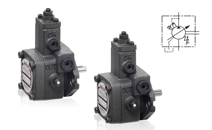
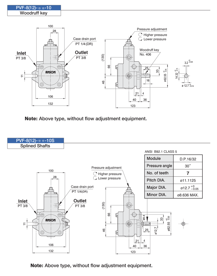
PVF-8(12) Series variable single vane Pumps
How to order:


Variable Displacement Vane Pumps
PVF Series-Single Pumps Model Code
| PVF |
-12 |
-70 |
-10 |
S |
| Frame size |
Outlet flow
(at 3.5bar,1800 r/min) |
Operating pressure range |
Design |
Shafts code |
| Code |
Outlet Flow L/min
(Geometric displacement cm3/rev) |
Code |
Pressure range
(bar) |
PVF:
Flange mounting |
8 |
8(5) |
20 |
8~20 |
10 |
Omit:
Woodruff key
S:
Splined Shafts |
| 12 |
12(7) |
35 |
15~35 |
| 15 |
15(8) |
55 |
30~55 |
| 20 |
20(12) |
70 |
50~70 |
| 30 |
30(16) |
Factory setting P min. |
| 40 |
40(22) |
| Factory setting Q max. |
※Pumps Speed Limits
Minimum speed:800 r/min
Maximum speed:1800 r/min
Vane pumps are available in two different types
A) specifically refers to the volumetric pump vane pump.
Refers to the three pumps (centrifugal pump, mixed flow pump, axial flow pump) or other special pumps of the power pump.
This type of pump products generally do not call vane pump. But as a monograph, vane pump almost all refers to centrifugal pump, mixed flow pump, axial flow pump, etc
According to the theoretical displacement per revolution is fixed or variable value, can be divided into vane variable pump and vane quantitative pump.
The working principle of
When the vane pump rotor rotates, the blade is under the action of centrifugal force and pressure oil, and the tip is close to the inner surface of the stator. In this way, the working volume formed by the two blades, the rotor and the inner surface of the stator starts from small to large to absorb oil first and then to discharge oil from large to small. When the blade rotates once, oil absorption and oil discharge are completed.
I. working principle of single-acting vane pump
The pump is composed of rotor 1, stator 2, blade 3, oil distribution plate and end cover, etc. The inner surface of the stator is cylindrical. There is eccentricity between rotor and stator. The blade can slide flexibly in the groove of the rotor. Under the action of centrifugal force when the rotor rotates and pressure oil flowing through the root of the blade, the top of the blade is attached to the inner surface of the stator. Thus, a sealed working chamber is formed between two adjacent blades, the oil distribution plate, the stator and the rotor. When the rotor rotates counterclockwise, the blade on the right side of the figure extends outwards, and the volume of the sealing chamber gradually increases, creating a vacuum. Therefore, oil is sucked through the upper window of oil suction port 6 and oil distribution plate 5. On the left. As the blade shrinks in, the volume of the sealing chamber gradually shrinks, and the oil in the sealing chamber is pressed out through another window of the oil distribution plate and oil pressure port 1 and then output to the system. This pump in the process of rotor rotation, oil suction pressure oil once, so called single action pump. The rotor is subjected to radial hydraulic unbalanced force, so it is also called non-balanced pump, its bearing load is large. The displacement of the pump can be changed by changing the eccentricity between the stator and rotor, so this pump is a variable pump.
The working principle of double acting vane pump
Its principle of action is similar to that of a single-acting vane pump, except that the stator surface is composed of eight parts, namely two long radius arcs, two short radius arcs and four transition curves, and the stator and rotor are concentric. In the case of clockwise rotation of the rotor shown in the figure, the volume of the sealing chamber increases gradually in the upper left and lower right corner, which is the oil absorption area, and decreases gradually in the lower left and upper right corner, which is the oil pressure area. There is a seal between the oil suction and pressure zones to separate them. This pump rotor every turn, each sealed chamber to complete oil absorption and oil pressure action twice, so called double action vane pump. The two oil suction area and two oil pressure area of the pump are radial symmetry, acting on the rotor of the hydraulic pressure radial balance, so also known as balanced vane pump.
The instantaneous flow rate of the double-acting vane pump is pulsating, and the pulsating rate is small when the number of blades is a multiple of 4. For this reason, the number of double-acting vane pump blade is generally 12 or 16.
Matters needing attention
Vane pump management points in addition to the need to prevent dry rotation and overload, prevention of inhalation of air and inhalation of vacuum is too large, but also should pay attention to:
1. Pump steering change, then its suction and exhaust direction also change the vane pump has a specified steering, not allowed to reverse. Because the rotor blade groove is inclined and the blade is chamfer, the bottom of the blade is connected with the oil discharge chamber, and the throttle groove, suction and discharge port on the oil distribution plate are designed according to the established steering direction. Reversible vane pumps must be specially designed.
2. Vane pump assembly oil distribution plate and stator with positioning pin positioning correctly, blade, rotor, oil distribution plate shall not be installed in reverse, the stator inner surface suction area part of the most easily worn, when necessary, can be turned to install, in order to make the original suction area into a discharge area and continue to use.
3. Attention to the cleaning of the working surface, working oil should be very good filtration.
4. Too much blade clearance in the blade groove will increase leakage, and too small blade cannot freely expand and contract, which will lead to abnormal work.
5. The axial clearance of a vane pump affects vertical v.
1) small pump -0.015 ~ 0.03mm
2) medium pump -- 0.02-0.045mm
6. Temperature and viscosity of the oil should not be commonly more than 55 ℃, the viscosity requirements between 17 ~ 37 was/s. Too much viscosity is difficult to absorb oil; Viscosity is too small leakage is serious.


