 |
Products list |
 |
|
| |
|
|
|
|
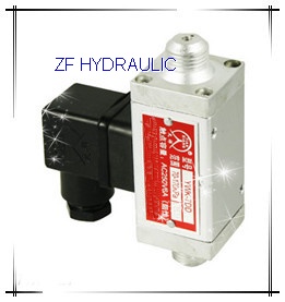
YWK-7DD Differential Pressure Switches |
|
| Product name : YWK-7DD Differential Pressure Switches |
| Item : |
| Details : |
YWK-7DD Differential Pressure Switches
 The sensor of this Switch is a Diaphragm-Piston combination, it can endure High Static Pressure, and can be suitable for air,gas and neutral gas, lubricant, light fuel etc. fluid medium. The differential pressure of the switches is adjustable, and its adjustable range is from 70Kpa to 300Kpa. with its compact structure, it is specially suitable for field which is critical on the mounting space.
Technical Performance:
Capacity
Working Viscosity:<1x10⁻³m2/s
Switching Elements:Microswitches
Ambient temperature:-25℃~55℃
Medium Temperature:-25℃~80℃
Mounting (The Hi-Pressure Cavity ) Pressure connection virtically downward (an angle of 15 is allowable)
Anti-Vibration:Max.100m/s2
Repeatablity Error:≤2.5%FS
Electrical rating :AC 220V ,6A(Resistance)
Characteristic
Good anti-vibration, microminiature design, High switching frequence (100 times/min.)
Specifications
Dead Band Non-Adjustable
 The Adjustment for Set Point(please refer to the Set-point Adjustment for Pressure Switches)
In-put the Hi-Pressure source at the H port, and In-put the Lo-pressure source at the L port.
Example: Choose Differential Pressure Adjustable Range from 70 to 170Kpa Switch, an alarm need to be generated when Differential Pressure rises to 120Kpa( the Increasing Set Point), specific steps please refer to followings:
1) Screw the Hi-Pressure port of the switch onto the Test-bench , and connect the plug with the source.
2) Add the pressure to 120Kpa, this value can be read from a standarded gauge.
3) Use the Socket Head Screw spanner (M2) to regulate the Set Point nut which is inside the Lo-Pressure connection (clockwise rotate the nut, the value will become larger; countrarotate the nut, the value will become smaller)
4)Varing the pressure up and down arround 120 Kpa, to check if it switches at 120Kpa, this is just the Increasing Set Point, its correspondent Decreasing Set Point is 120Kpa minus Dead Band (approximately 30Kpa), to be 90Kpa(approximately)
(If the user do not have correspending tools ,then this step can be canceled.)
Selection and Installation (Please refer to the selection and Installation of Switches)
The Set Point must be within the aAdjustable Range, Dead Band is expressed as Typical at mid-range. Normally it is the 20% to80% of the Ajustable Range.
The On-Off current should not exceed the Rating (when the contacts act frequently, the current better not to exceed the 60% of the Rating.)
If the switches are outdoor application, sufficient protections are necessary, for the severe variation of the ambient temperature, radiation of the sunlight, permeation of the corrosive gas or water, will influence the life of the switches.
Regarding those controlled fluid medium with peak value of pressure and plusation pressure, a damper can be installed at the connection, to eliminate negative influence
During the process of installation or disassembly, a spanner MUST be used to clip and tighten the connection part of the sensor,to prevent the housing and the Hi-pressure &Lo-pressure connections become flexiable.
Please earthen the plug reliably.
Do not oppositely connect the Hi-pressure and Lo-pressure port, otherwise it would not work.
 |
 |
←[Previous : ]
[Next : ]→
|
|


 Pressure switch


