|
Products list |
 |
|
| |
|
|
|
|
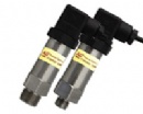
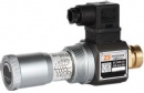
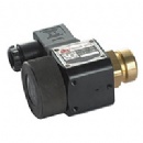
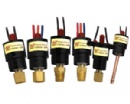
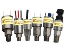
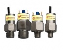
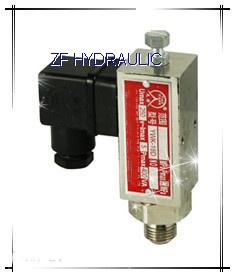
YWK-18D Pressure Switches |
|
| Product name : YWK-18D Pressure Switches |
| Item : |
| Details : |
YWK-18D Pressure Switches
 The sensor of Switches is Diaphragm type, it has advantages as Hi-pressure endurable, long working life,compact structure.the enclosure is made of high-class stainless materials, solid and durable. With our special sensor, YWK-18D Switches
Technical Performance:
Working Viscosity:<1x10⁻³m2/s
Ambient temperature:-25℃~+55℃
Medium Temperature: -25℃~+80℃
Mount Position:Pressure connection virtically downward (15°inclination is allowed)
Protection Class of Enclosure: IP65
Anti-Vibration:Max:100m/s2
Repeatablity Error: ≤2%
Working Life:1x10⁵
Weight:0.23kg
Electric Rating:AC 220V 6A(resistance)
Specification
Dead Band Non-Adjustable
The sensor of Switches is Diaphragm type, it has advantages as Hi-pressure endurable, long working life,compact structure.the enclosure is made of high-class stainless materials, solid and durable. With our special sensor, YWK-18D Switches
Technical Performance:
Working Viscosity:<1x10⁻³m2/s
Ambient temperature:-25℃~+55℃
Medium Temperature: -25℃~+80℃
Mount Position:Pressure connection virtically downward (15°inclination is allowed)
Protection Class of Enclosure: IP65
Anti-Vibration:Max:100m/s2
Repeatablity Error: ≤2%
Working Life:1x10⁵
Weight:0.23kg
Electric Rating:AC 220V 6A(resistance)
Specification
Dead Band Non-Adjustable
 Remarks: In the practice, even the temporal peak value of pressure ,should no exceed the Max. Allowable Pressure.
Special requirements on Dead Band or Connection can be designed customized
The Adjustment for Set Point
[Example] Choose Switch with Pressure Range from 2.4Mpa to 24Mpa , a contact signal is required to be generated
Remarks: In the practice, even the temporal peak value of pressure ,should no exceed the Max. Allowable Pressure.
Special requirements on Dead Band or Connection can be designed customized
The Adjustment for Set Point
[Example] Choose Switch with Pressure Range from 2.4Mpa to 24Mpa , a contact signal is required to be generated
when pressure falls to 15Mpa(The Decreasing Set Point), see steps as following:
To screw the switch into connection of Oil Pressure Checkout Test Set. Exert pressure on it for 2 minutes simulate its
practical working situation, thereafter to make the setting.
Link the Out-put lead with Multimeter.
Screw-off the screws on the housing.
Add the pressure to 15Mpa, this value can be read from the standarded pressure gauge.
Use socket screwwrench (Φ3mm), clockwise rotate the Set-point Adjusting Bolt, to make the Set-Point become bigger,until it switches at 15Mpa.
Vering the testing pressure to make it change up and down arround 15Mpa, check if the Switch switches at 15Mpa
when pressure falls, this value is the Decreasing Set Point need to be set, the correspondent Increasing Set Point is
within 16.9Mpa to 18Mpa.
Tighten the Locknut.
While removing the cover, please do not touch the components inside the switches.
The Set Point must be within the aAdjustable Range, Dead Band is expressed as Typical at mid-range. Normally it is the 20% to80% of the Ajustable Range.
If the switches are outdoor application, sufficient protections are necessary, for the severe variation of the ambient
temperature, radiation of the sunlight, permeation of the corrosive gas or water, will influence the life of the switches.
During the process of installation or disassembly, a spanner MUST be used to clip and tighten the sensor, absolutely
avoid the countermovent between the sensor and housing of the switches(please refer to the drawings)
 |
 |
←[Previous : ]
[Next : ]→
|
|


 Pressure switch