IVPV Series Double vane Pumps
How to order:


Intravane Fixed Displacement Vane Pumps
IVP(Q/V) Model Code - Double Pumps
| F3- |
IVP (Q/V)21 |
-17 |
H |
-12 |
H |
A |
M |
-F |
-R |
-86 |
AA |
-10 |
| Prefix, Fluid Compatibility |
Frame Size |
Geometric Displacement
●Code |
Pressure type
★ |
Geometric displ. cover end pump
●Code |
Pressure type
★ |
Port connections |
Port connections
modifier |
Mounting Form |
Shaft Rotation |
▲Shaft model |
Port orientation |
Design |
| Str. key |
HD Str. key |
Splined key |
Omit:
Using Petroleum Base oil & anti-wear hydraulic oil
F11-
Using water glycol fluid.
F3-
Using water-in-oil emulsions or phosphate ester fluid. |
IVP(Q/V)21 |
10, 12, 14, 15, 17, 19, 21, 25 |
|
2, 3, 4, 5, 6, 7, 8, 10, 11, 12, 14 |
|
|
|
|
Viewed from shaft end of pump
|
1 |
86 |
11 |
Viewed from cover end of pump
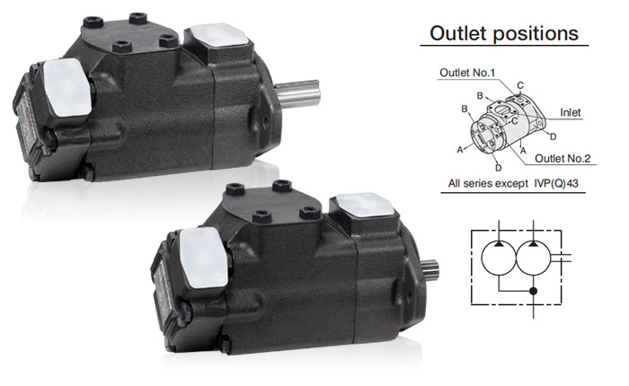
With no.1 outlet opposite inlet
AA-
No.2 outlet 135˚CCW from inlet
( NO.2 outlet opposite inlet )
AB-
NO.2 outlet 45˚CCW from inlet
( NO.2 outlet 90˚CCW from inlet)
AC-
No.2 outlet 45˚CW from inlet
( No.2 outlet inline with inlet )
AD-
No.2 outlet 135˚CW from inlet
( No.2 outlet 90˚CW from inlet )
With no.1 outlet 90˚CCW from inlet
BA-
No.2 outlet 135˚CCW from inlet
( NO.2 outlet opposite inlet )
BB-
NO.2 outlet 45˚CCW from inlet
( NO.2 outlet 90˚CCW from inlet)
BC-
No.2 outlet 45˚CW from inlet
( No.2 outlet inline with inlet )
BD-
No.2 outlet 135˚CW from inlet
( No.2 outlet 90˚CW from inlet )
With no.1 outlet inline with inlet
CA-
No.2 outlet 135˚CCW from inlet
( NO.2 outlet opposite inlet )
CB-
NO.2 outlet 45˚CCW from inlet
( NO.2 outlet 90˚CCW from inlet)
CC-
No.2 outlet 45˚CW from inlet
( No.2 outlet inline with inlet )
CD-
No.2 outlet 135˚CW from inlet
( No.2 outlet 90˚CW from inlet )
With no.1 outlet 90˚CW from inlet
DA-
No.2 outlet 135˚CCW from inlet
( NO.2 outlet opposite inlet )
DB-
NO.2 outlet 45˚CCW from inlet
( NO.2 outlet 90˚CCW from inlet)
DC-
No.2 outlet 45˚CW from inlet
( No.2 outlet inline with inlet )
DD-
No.2 outlet 135˚CW from inlet
( No.2 outlet 90˚CW from inlet )
|
10 |
| IVP(Q/V)31 |
17, 21, 25, 30, 32, 35, 38, 42 |
Omit –
Standard pressure
|
2, 3, 4, 5, 6, 7, 8, 10, 11, 12, 14 |
Omit –
Standard pressure
|
A-
SAE 4 bolt flange |
M-
Metric
(4-bolt flange)
|
F-
Flange
mounting |
R-
Right hand for clockwise |
1 |
86 |
11 |
| IVP(Q/V)32 |
17, 21, 25, 30, 32, 35, 38, 42 |
H-
High pressure |
10, 12, 14, 15, 17, 19, 21, 25 |
H-
High pressure |
|
Omit - Inch
(4-bolt flange) |
L-
Foot
mounting |
L-
Left hand for counter-clockwise |
1 |
86 |
11 |
| IVP(Q/V)41 |
30, 35, 38, 42, 50, 60, 67, 75 |
|
2, 3, 4, 5, 6, 7, 8, 10, 11, 12, 14 |
|
|
|
|
|
1 |
86 |
11 |
| IVP(Q/V)42 |
30, 35, 38, 42, 50, 60, 67, 75 |
|
10, 12, 14, 15, 17, 19, 21, 25 |
|
|
|
|
|
1 |
86 |
11 |
| IVP(Q/V)43 |
30, 35, 38, 42, 50, 60, 67, 75 |
|
17, 21, 25, 30, 32, 35, 38, 42 |
|
|
|
|
|
1 |
86 |
11 |
| |
|
|
|
|
|
|
|
|
|
|
|
● Rated capacity in US gpm at 1200r/min and 6.9bar(100psi).
★ IVPQ series no H high pressure type.
▲ IVPQ series no splined Shaft model.
Single-acting vane pump is composed of stator, rotor, blade and main parts such as flow distribution. The stator is made of wear-resistant material. The rotor is provided with a blade groove in which the blade is mounted and slides. The rotor and stator are eccentrically arranged with eccentricity e, and the distribution plates on both sides are closely fitted. When the motor drives the rotor to rotate, the blade clings to the inner surface of the stator under the action of centrifugal force or spring force or liquid pressure. In this way, a number of sealing working volumes are formed between the stator, rotor, blade and distribution plate. When the rotor rotates in the direction shown in the figure, the right blade gradually extends outward, and the sealing volume between the blades gradually increases, forming a local vacuum. The oil is sucked through the suction window on the distribution plate (as shown by the dotted line in the figure) from the suction port of the pump. On the left side of the rotor, the blade is forced to retract under the action of the stator, and the sealing volume between the blades is gradually reduced, and the oil is discharged from the discharge window on the flow distribution plate. Every rotation of the rotor completes a suction and discharge for each working volume, so it is called a single-acting vane pump. Single acting vane pump eccentricity e can be changed. Change the size of e can change the pump displacement. If the eccentric direction changes, the pump suction and discharge direction also changes. In order to balance the pressure at both ends of the blade in the discharge area, so as to smoothly slide out of the rotor slot under the action of centrifugal force and stick to the stator surface, the bottom of these blade slots is usually connected with the discharge cavity; The bottom of each blade groove located in the suction area is communicated with the suction cavity to avoid the blade end and the stator being pressed too tightly, thus reducing their wear. Single-acting vane pump side is low pressure, one side is high pressure, pump shaft and bearing to bear a large radial load. Therefore, the single-acting vane pump is also called non-equilibrium vane pump, which limits the increase of the working pressure of the single-acting vane pump.
|


