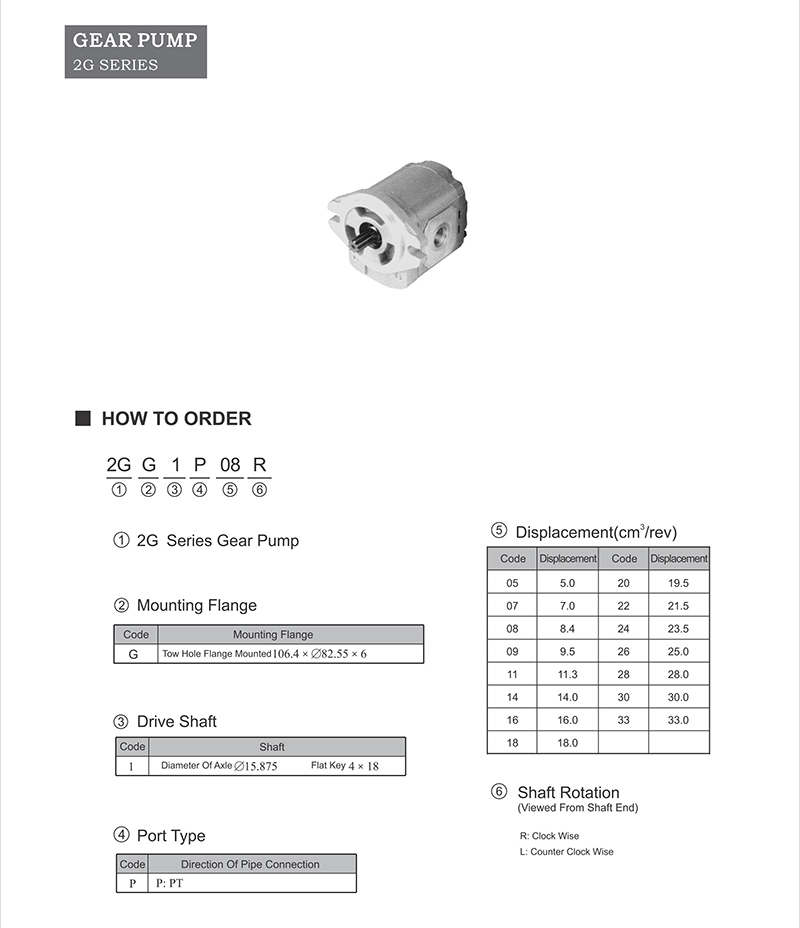
2G gear pump
How to order:

Working principle and displacement calculation method of oil suction and pressure in external gear pump
1. Working principle of gear pump
When the driving gear rotates according to the direction shown in the figure, the gear teeth in the lower oil suction chamber are out of engagement, and the volume of the sealed cavity is continuously increased, and a certain vacuum degree is formed in the cavity. Atmospheric pressure pushes the oil into the oil suction chamber, which is called "oil absorption".
The gear pump
With the rotation of the gear, the oil filled in the gear groove is brought to the upper oil discharge chamber by the rotating gear tooth valley according to the direction of arrow, and the gear tooth continuously enters the nibbling, so that the volume of oil discharge (seal chamber) is reduced, and the oil is squeezed and discharged to the system from the pressure yi mouth, which is the working principle of oil absorption and oil pressure of the gear pump.
Gear pump working principle
Transfer only oil in a volume - invariant section. Gear pump does not need oil distribution device, but can not variable (figure 1). Displacement: 0.2 ~ 200cm3; Maximum pressure: 300bar (depending on size); Speed range: 500 ~ 6000r/min.
Gear pump working principle
2. Gear pump displacement calculation method
Q = 2 PI K1Z ㎡ / bn x 10-3 (negative power three)
In the formula, the q-1 displacement is mL/r;
K-1 is the coefficient related to the overlap coefficient of gear engagement, usually K1= l.06 ~ l.115. When the number of teeth is small, the value is large; when the number of teeth is large, the value is small.
Z one teeth;
M one module, mm;
B - tooth width. Mm;
N one speed, r/min.


